Trending

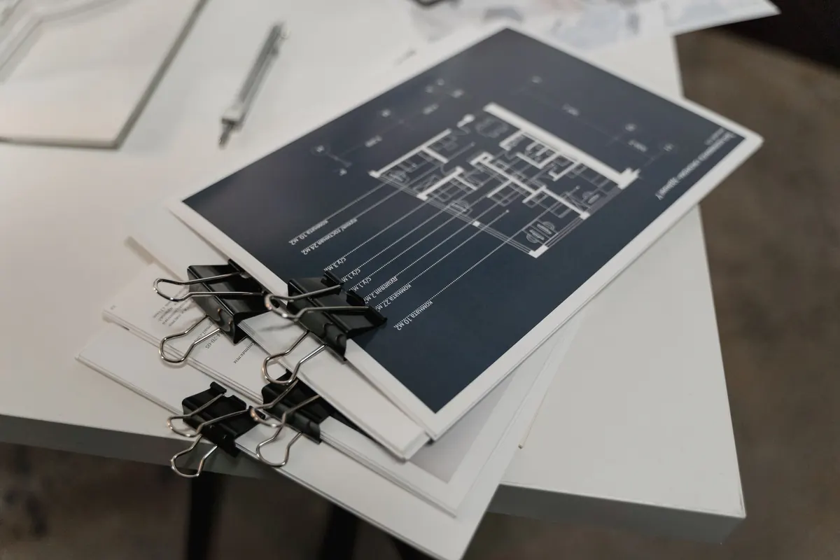
A rolled A1 sheet arrives from a studio in Bologna, and on the table it looks less like a drawing than a weather map: grey outlines, red circles, little triangles with letters beside them, and a column of numbers in the bottom right corner. Bridge drawings from Italy reward patience. They are built on a small set of conventions that repeat from project to project, and once you recognise those conventions, a dense sheet turns into something you can actually argue with.
This guide covers the conventions you will meet on new-build and repair drawings alike — the ones produced for concrete road bridges, masonry arch repairs, and the small pedestrian crossings that appear in so many Italian towns. It assumes no drafting experience, only an interest in what the structure is doing.
The title block sits in the bottom right corner and Italians call it the cartiglio. Read it before anything else. It tells you the project name, the client (a Comune, a Provincia, ANAS, RFI, a private developer), the drawing number — often written as Tav. 04 — the scale, the date, and the revision.
Check the revision first. A sheet marked rev. 02 with a later date may have moved a pier by half a metre, and the copy in your hand may be the one from before. Italian drawing sets also carry a scale hierarchy: 1:500 or 1:1000 for the general layout, 1:100 or 1:50 for the bridge itself, 1:20 down to 1:5 for details. Anything marked N.T.S. (not to scale) is diagrammatic — useful for reinforcement arrangement, useless for measuring.
Almost every Italian bridge sheet is organised around three views, and they are meant to be read together.
Pianta — the plan. You look down on the bridge. This is where the alignment, the road width, the footpath widths, the pier positions and the chainage along the bridge axis appear. Chainage is written as prog. (progressiva) in metres, so prog. 125,40 is a point 125.40 m along the axis. For a river crossing, the plan usually includes the waterway outline and the flood section.
Prospetto — the elevation. You see the bridge from the side: span arrangement, deck depth, the shape of the piers, the height above ground or water, the clearance under the soffit. This is where a bridge's proportions live, and it is the view a non-specialist reads most easily.
Sezione — the section. A slice through the structure, usually transverse. Here you find the deck build-up: slab thickness, number and depth of girders, edge beams (cordoli), waterproofing, wearing course, drainage, and the bearings sitting on their plinths (pulvini) on top of the piers. Longitudinal sections do the same job along the bridge and show foundation depth.
A useful habit: never read one view alone. If a pier looks strangely wide in elevation, the section will tell you why — a hammerhead cap, a skew, or a bearing shelf that has to carry the deck's movement.
Cutting lines run across the plan with arrows at each end and matching letters: A—A, B—B. The arrows show the direction of view, so a section marked A—A on the plan corresponds to the drawing labelled Sezione A—A elsewhere on the sheet or on another sheet.
Details are pulled out with a circle or a small box containing a number, plus a reference such as part. 3, Tav. 07 — detail 3, sheet 7. You will also see notes like v. part. (see detail) and v. tav. (see sheet). Follow these references. Most of the information that decides whether a repair is buildable hides in the details at 1:10: a bearing replacement, a joint nosing, a bar anchorage into existing concrete.
Italian practice follows the UNI standards, which for line types and sheet layout largely mirror the international ISO conventions. The grammar is consistent enough to learn in an afternoon:
Hatching carries meaning too. Concrete is often shown with a fine stipple or aggregate pattern; reinforced concrete adds bars as thick dots in section and heavy lines in elevation; structural steel is usually shown solid or with a diagonal hatch; masonry in an arch repair comes with an irregular block pattern. Ground below a foundation gets its own hatch, and the level at which it stops is the founding level.
Small symbols do a lot of quiet work: a rectangle with layered lines is a bearing; two parallel lines with a gap between them is an expansion joint; a circle on the deck edge is a drainage outlet; a thick dashed band over the slab is waterproofing; a curved dash-dot line with an anchor block at each end is a post-tensioning tendon. Coloured circles and handwritten clouds are usually someone's review markup, not part of the original drawing — useful, but never authority.
Dimensions appear in chains: an overall dimension, then intermediate ones, all tied to the same reference points. Add up the intermediate figures and check they equal the total. Discrepancies happen, and catching one early is far cheaper than catching it on site. Note the units — Italian structural drawings are often dimensioned in centimetres or millimetres, while levels (quote altimetriche) are almost always in metres with a comma as decimal separator, so quota 12,45 means 12.45 m. Check what the zero refers to: sea level, or a local benchmark such as the deck soffit at mid-span.
Reinforcement is written compactly. Ø20/15 means 20 mm bars at 150 mm centres; n. 6 Ø20 means six bars. Stirrups appear as staffe Ø10/20, concrete as a class such as C30/37, steel as a grade such as B450C. Cover (copriferro) is given once and applies everywhere unless noted. If you are checking a repair, look for the anchorage lengths and the dowel spacing — those numbers, not the general arrangement, determine whether the new concrete will act with the old.
Repair sets are often split into stato di fatto (existing condition) and stato di progetto (proposed). Elements to be demolished are dashed, crossed out, or hatched in a distinct pattern; new work is drawn heavier, sometimes in a different colour, and marked with the phase in which it happens. On a bridge that must stay open, the phasing notes matter as much as the geometry.
Watch for conditional notes such as verificare in opera (verify on site) or da confermare in corso d'opera (to be confirmed during construction). They are honest signals that the designer could not see inside the concrete and that quantities may change. Pair the drawing with the accompanying relazione and computo metrico before forming a view on cost or programme.
When a new set lands, work through it in the same order every time. It saves you from the classic mistake of studying a detail before knowing where it sits.
Do that a few times and the sheets stop looking like weather maps. They start looking like a set of decisions someone made, in a particular order, with reasons you can now follow — and question, politely, when something does not hold together.
Photo: Tima Miroshnichenko / Pexels